AKT3040E-10 Amana Range - Overview
Sections of the AKT3040E-10
[Viewing 1 of 1]Keep searches simple, eg. "belt" or "pump".

Dual Surface Burner Switch Kit
PartSelect #: PS2003583
Manufacturer #: 12002125
This switch is used to operate the dual surface burner.
$54.01
In Stock

Radiant Surface Burner Element
PartSelect #: PS11764909
Manufacturer #: W10823699
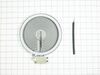
This surface element is made for under glass set-ups and supplies the heat to a cooking area on top of the range. It has an outside diameter of approximately 7 inches (1500 watts), and is a genuine OE...
$93.60
In Stock

Refrigerator Screw
PartSelect #: PS11742713
Manufacturer #: WP488234
This screw is sold individually.
Size: 8-32 x 1/4 inch.
$8.95
Special Order

Dual Burner Knob
PartSelect #: PS2034011
Manufacturer #: 31926603B
This knob is used for a dual burner and takes a double-flat shaft.
No Longer Available

Surface Ribbon Element with Limiter - Small
PartSelect #: PS11741007
Manufacturer #: WP32082801
This is a 1200 watt / 240 volt surface element.
No Longer Available

ELMNT-SURF
PartSelect #: PS11764913
Manufacturer #: W10823708
This is a 2000 watt / 240 volt surface element.
$119.51
Special Order
Questions And Answers for AKT3040E-10
Be the first to ask our experts a question about this model!
✖
Ask a Question
Ask our experts a question on this model and we'll respond as soon as we can.
Sorry, we couldn't find a match for "".
Here's a guide for finding your model number.
Something went wrong. Please try again later.
Your Question Has Been Submitted!
Our experts will send you an email as soon as your question has been answered.
Common Symptoms of the AKT3040E-10
[Viewing 2 of 2]Keep searches simple. Use keywords, e.g. "leaking", "pump", "broken" or "fit".
Outer element of dual element burner didn't work
Remove Ceran Galss top by removing hex screws below the rim. Also remove the two opposing screws in the center of the downdraft opening. Ceran top comes off easily now.
The instructions with the new switch were very poorly written, so here is how I got the new switch to work:
Attach the black wire(s) from the old switch (termi ... Read more nal 2) to the new switch terminal P1. Also attach the jumper cable to P1 and "jump" it to S1.
Attach the orange wire (old switch terminal 5) to S2
Attach the yellow wire (old switch terminal 4) to 4a
Attach the tan/(white?) wire (old switch terminal 3) to terminal 4 on the new switch
Attach the single red wire from the right front element to terminal 2 on the new switch.
Attach the 'compound' red wires (the ones that come from the left rear/outlet connection and is also attached to the right rear switch) to terminal P2 on the new switch.
There is no need to seperate the compound red wires as the instructions might lead you to believe.
Good Luck
Read less
Parts Used:
-
Michael from Collierville, TN
-
Difficulty Level:A Bit Difficult
-
Total Repair Time:30 - 60 mins
-
Tools:Nutdriver, Pliers, Socket set
140 of 183 people
found this instruction helpful.
Was this instruction helpful to you?
Thank you for voting!
The repair itself was very easy. “How to connect” was very hard to get.
To get access to the switch, unscrew 2 screws from each side of front panel and then 4 screws from the bottom of it (open the door first). Have a box or a small table about 30” high to use it as support for the front panel.
The end result ... Read more (colors for the Right Front- R.F.- burner) : Old label -> New label
1. Double RED: N -> P2 (incoming power, Line 1)
2. Single RED: N -> 2 (to Inner AND Outer heating elements common wire)
3. Single BLK: L1 -> P1 (incoming power, Line 2)
4. Single TAN: H1 -> 4 (to the Inner heating element)
5. Single YEL: H2-> 4a (to the Inner heating element)
6. Single BLK: P -> S2 (to the R.F. indicator control light)
7. Attach jumper black wire (included with new switch) from P1 (P1 has two connectors close together) to S1.
Done.
Read less
Parts Used:
-
Igor from Campbell, CA
-
Difficulty Level:Really Easy
-
Total Repair Time:15 - 30 mins
-
Tools:Nutdriver, Pliers, Screw drivers
53 of 62 people
found this instruction helpful.
Was this instruction helpful to you?
Thank you for voting!
Jenn Air Dual element switch broke
This is not at hard as it seems; I followed the first guy's story and ignored the colors because mine were different. I did have to split the combined red wires, intimidating at first but once I split them it was down hill.
I did have to use the jumper wire.
Follow
Appliance Repaired: Jenn-Air Range/Stove/Oven/H ... Read more ood
Model: cve3401b
Age Of Appliance: 5 - 10 years
Remove Ceran Galss top by removing hex screws below the rim. Also remove the two opposing screws in the center of the downdraft opening. Ceran top comes off easily now.
The instructions with the new switch were very poorly written, so here is how I got the new switch to work:
Attach the black wire(s) from the old switch (terminal 2) to the new switch terminal P1. Also attach the jumper cable to P1 and "jump" it to S1.
Attach the wire from old switch terminal 5)to S2
Attach the wire from old switch terminal 4 to 4a
Attach the wire from old switch terminal 3 to terminal 4 on the new switch
Detach the 'compound' red wires from each other.
(The ones that come from the left rear/outlet connection and is also attached to the right rear switch) to terminal P2 on the new switch.
I attached common female connectors.
Attach the newly split single red wire from the right front element to terminal 2 on the new switch.
One note:
Before you remove the four screws that hold the four swtiches down make sure that you use a sharpie and mark the switchbox location. You will notice that it is difficult to get them to line up again with the holes in the cooktop.
Thanks partselect.com!
Read less
Parts Used:
-
Todd from Concord, OH
-
Difficulty Level:A Bit Difficult
-
Total Repair Time:30 - 60 mins
-
Tools:Nutdriver
15 of 21 people
found this instruction helpful.
Was this instruction helpful to you?
Thank you for voting!